In order to move on to simulating a grid connected inverter, the next step is to implement a Phase Locked Loop (PLL). The method used is the synchronous transfer frame reference alignment. In more detail, starting with a frequency that could be close to what could be the normal frequency, using a Proportional Integral (PI) controller, we adjust the frequency until the signal being locked on to is aligned with the reference frame. So with the frequency being adjusted, calculate the d and q axis components in the rotating reference frame, and adjust the frequency until the q component is zero.
The circuit is pretty simple:

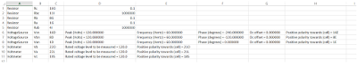
There is an unbalanced three phase resistor bank connected across a three-phase voltage source. Well it doesn't really matter, because we just want the voltage source. The parameters of the circuit are:
Run-time parameters:
-------------------------------------------------------------------------------------------------------------------------
>>>
CSV file containing the network layout --> grid_pll
Enter parameters in file grid_pll_params.csv. When done, close the file and press y and enter to continue -> y
**************************************************
Voltmeter is Vb located at 22O with positive polarity towards 21O
Voltmeter is Va located at 22L with positive polarity towards 21L
Voltage Source is Vcn of 120.000000 V(peak), 60.000000 Hz(frequency), -240.000000 (degrees phase shift) and 0.000000 dc offset located at 16D with positive polarity towards 16E
Resistor is Rc = 0.100000 located at 16G
Resistor is Rbc = 1000000.000000 located at 11I
Resistor is Rb = 0.100000 located at 8G
Voltage Source is Vbn of 120.000000 V(peak), 60.000000 Hz(frequency), -120.000000 (degrees phase shift) and 0.000000 dc offset located at 8D with positive polarity towards 8E
Voltmeter is Vc located at 19S with positive polarity towards 18S
Voltage Source is Van of 120.000000 V(peak), 60.000000 Hz(frequency), 0.000000 (degrees phase shift) and 0.000000 dc offset located at 1D with positive polarity towards 1E
Resistor is Ra = 0.100000 located at 1G
Resistor is Rab = 1000000.000000 located at 4I
**************************************************
Enter the control files. Omit the .py extension and just leave spaces between files --> pll_3ph
Enter control parameters in the following files -->
pll_3ph_desc.csv
When ready press y and enter to continue -> y
Enter control code in the following files -->
pll_3ph.py
When ready press y and enter to continue -> y
**************************************************
Meters are in the following sequence: ['19S', '22L', '22O']
Control variables to be plotted are in the following sequence
['control_signal1', 'control_signal3', 'control_signal2', 'control_signal4']
**************************************************
Simulation time step in seconds (recommended <= 10.0e-6) --> 10.0e-6
Duration of simulation in seconds --> 1.0
Data storage time step in seconds ( >= 0.000010) --> 10.0e-6
Output data file name (.dat extension will be added) --> ckt_out
Data stored in ckt_out.dat. Check output log file output_log.txt for description of output
35.8410000801
-------------------------------------------------------------------------------------------------------------------------
In this case, there is a control file called pll_3ph even though there is no controllable element. VoltageSource, Resistor and Voltmeter are the only components in the circuit. In this case, the control file does not perform any control but is merely a signal processing code that generated control_signal1, control_signal2, control_signal3, control_signal4.
I will skip the details of the control and move on to the results. The control_signals 1,2,3,4 generated by the control code are
control_signal1 --> volt_d i.e d component of the voltage in the rotating reference frame
control_signal2 --> volt_q i.e d component of the voltage in the rotating reference frame
control_signal3 --> omega i.e angular frequency of rotating reference frame and the system
control_signal4 --> phase_angle of the sinusoidal signals
So first and foremost, frequency:

In steady state tracks 377 rad/s which is 2*pi*60.
Next, volt_q:

As stated above in the principle of operation of the PLL, in steady state the q component of voltage in the rotating reference frame will be zero. This is when the rotating frame is at the same frequency as that of the source.
Next, volt_d:

The d component of the voltage settles to 147V. This is the Root Mean Square (RMS) value of the Line to Line (L-L) voltage of the system. There are several forms of transformations that use several multiplying factors that could case d component to have all kinds of values - peak of Line to Line, peak of phase etc.
The last is the phase angle. This needs to be plotted with the a component of the voltage to give you an idea of the alignment.

The way the component VoltageSource generates voltage is as a sine template with respect to time. As seen above, the phase angle starts at 0 from the peak of what is the "a" phase voltage. This is because the PLL uses cosine and sine templates of the phase angle to align the rotating reference frame. The cosine of the above phase angle will therefore turn out to be a cosine function corresponding to the sine waveform of the voltage.
The next step is including a notch filter to make sure the PLL works even when the grid is unbalanced. After which I can simulate a grid connected inverter.
Questions or comments? Send an email to pythonpowerelectronics@gmail.com.
The circuit is pretty simple:

There is an unbalanced three phase resistor bank connected across a three-phase voltage source. Well it doesn't really matter, because we just want the voltage source. The parameters of the circuit are:

Run-time parameters:
-------------------------------------------------------------------------------------------------------------------------
>>>
CSV file containing the network layout --> grid_pll
Enter parameters in file grid_pll_params.csv. When done, close the file and press y and enter to continue -> y
**************************************************
Voltmeter is Vb located at 22O with positive polarity towards 21O
Voltmeter is Va located at 22L with positive polarity towards 21L
Voltage Source is Vcn of 120.000000 V(peak), 60.000000 Hz(frequency), -240.000000 (degrees phase shift) and 0.000000 dc offset located at 16D with positive polarity towards 16E
Resistor is Rc = 0.100000 located at 16G
Resistor is Rbc = 1000000.000000 located at 11I
Resistor is Rb = 0.100000 located at 8G
Voltage Source is Vbn of 120.000000 V(peak), 60.000000 Hz(frequency), -120.000000 (degrees phase shift) and 0.000000 dc offset located at 8D with positive polarity towards 8E
Voltmeter is Vc located at 19S with positive polarity towards 18S
Voltage Source is Van of 120.000000 V(peak), 60.000000 Hz(frequency), 0.000000 (degrees phase shift) and 0.000000 dc offset located at 1D with positive polarity towards 1E
Resistor is Ra = 0.100000 located at 1G
Resistor is Rab = 1000000.000000 located at 4I
**************************************************
Enter the control files. Omit the .py extension and just leave spaces between files --> pll_3ph
Enter control parameters in the following files -->
pll_3ph_desc.csv
When ready press y and enter to continue -> y
Enter control code in the following files -->
pll_3ph.py
When ready press y and enter to continue -> y
**************************************************
Meters are in the following sequence: ['19S', '22L', '22O']
Control variables to be plotted are in the following sequence
['control_signal1', 'control_signal3', 'control_signal2', 'control_signal4']
**************************************************
Simulation time step in seconds (recommended <= 10.0e-6) --> 10.0e-6
Duration of simulation in seconds --> 1.0
Data storage time step in seconds ( >= 0.000010) --> 10.0e-6
Output data file name (.dat extension will be added) --> ckt_out
Data stored in ckt_out.dat. Check output log file output_log.txt for description of output
35.8410000801
-------------------------------------------------------------------------------------------------------------------------
In this case, there is a control file called pll_3ph even though there is no controllable element. VoltageSource, Resistor and Voltmeter are the only components in the circuit. In this case, the control file does not perform any control but is merely a signal processing code that generated control_signal1, control_signal2, control_signal3, control_signal4.
I will skip the details of the control and move on to the results. The control_signals 1,2,3,4 generated by the control code are
control_signal1 --> volt_d i.e d component of the voltage in the rotating reference frame
control_signal2 --> volt_q i.e d component of the voltage in the rotating reference frame
control_signal3 --> omega i.e angular frequency of rotating reference frame and the system
control_signal4 --> phase_angle of the sinusoidal signals
So first and foremost, frequency:

Next, volt_q:

As stated above in the principle of operation of the PLL, in steady state the q component of voltage in the rotating reference frame will be zero. This is when the rotating frame is at the same frequency as that of the source.
Next, volt_d:

The d component of the voltage settles to 147V. This is the Root Mean Square (RMS) value of the Line to Line (L-L) voltage of the system. There are several forms of transformations that use several multiplying factors that could case d component to have all kinds of values - peak of Line to Line, peak of phase etc.
The last is the phase angle. This needs to be plotted with the a component of the voltage to give you an idea of the alignment.

The way the component VoltageSource generates voltage is as a sine template with respect to time. As seen above, the phase angle starts at 0 from the peak of what is the "a" phase voltage. This is because the PLL uses cosine and sine templates of the phase angle to align the rotating reference frame. The cosine of the above phase angle will therefore turn out to be a cosine function corresponding to the sine waveform of the voltage.
The next step is including a notch filter to make sure the PLL works even when the grid is unbalanced. After which I can simulate a grid connected inverter.
Questions or comments? Send an email to pythonpowerelectronics@gmail.com.
No comments:
Post a Comment